February 28th, 2010 — 11:54pm
What makes it possible for an amateur like me to take on a project like this is the overwhelming amount of support that comes from a worldwide community of developers, often without their knowledge. For example, the circuit design and firmware for the icetube clock are freely available to download and re-use under an open-source licence. The clock design is similar in some ways to my own. The schematics and code don’t have everything I’ll need in the final design, but I have learned a great deal and saved hours, days, maybe weeks worth of time in procurement and experimentation, and this gave me a great tutorial for developing my own design.
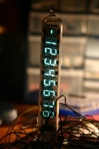
I was able to light up the IV-18 tube and have it display digits, without completely understanding how it all works. I guess this is the real beauty of open-source. You don’t have to know everything, you don’t have to do everything. You find something and build on it, and bring your own contribution.
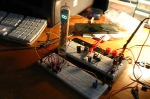
For this prototype I am using an obsolete HV518P high-voltage driver IC, which takes signals from the microcontroller and outputs high-voltage directly to the display segments in the VFD tube. I chose this one mainly because it comes in a DIP package, so I can fit it into a breadboard.
The most difficult part of getting all this to work was wiring from the driver to the VFD tube. The schematics for the icetube were for the popular MAX6921 driver, which I will likely use in the final design, but the wiring for the HV518 seems to be a bit different – so I had to cross-reference the icetube schematic and the data sheet for the HV518 to know which pins went where, which didn’t seem to work so well. It can be a bit like a rubix cube – even if it’s off by just one bit, it can take hundreds of re-tries to get it all in order. In the end I got it working by sheer brute force and determination.


Comments Off on Multiplexing with IV-18 | Alarm Clock Project, Electronics
February 27th, 2010 — 3:20pm
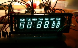
I bought a bunch of these VFDs last year for a bargain. I may use these for the first version of the clock. The have a nice large display with an extra 2 digits, an alarm indicator, and indicators for the day of the week.

Comments Off on Futaba 6-LT-23Z | Alarm Clock Project, Electronics
February 26th, 2010 — 12:38am
Over past year I have had a few meetings with Brent Rouke about the case for the alarm clock. By the summer we had developed a prototype for the case, and in the fall I had some custom glass cut to match the face. Here is the result:

Comments Off on Case Design Prototype | Alarm Clock Project
February 26th, 2010 — 12:30am
One of the challenges of working with a project like this that uses “exotic displays” such as Vacuum Fluorescent or Nixie Tubes is that these displays are very fickle with the way they are driven. VFDs typically need about 20-80 volts to light up the anode/grid segments of the display, and because they are vacuum tubes, they also need a filament to be heated up with about 1-5 volts.
There are a variety of ways to get the higher voltages. If the tubes you are using are not too picky you might get away with 12-24 volts, but if you want to support a variety of displays, and if you want to be able to drive the displays with multiplexing (i.e. flashing the segments+digits one at a time, in rapid succession), then you will need up yo 80v.
I have very little knowledge of analog circuitry and switch-mode power supplies, so I wanted to change that, and researched various ways to get the voltages I would need, and settled on a switch-mode PSU based on the MAX1771 step-up converter. After some trial and error with procuring the right components, I settled on a design based on this switch-mode power supply. This circuit was designed for nixies, which need up to 250 volts. It’s overkill for my current requirements but I want to support a variety of displays, and may use nixies at some point.
It took me a long time to get this working and I smoked a few mosfets and 1771s along the way, so it was pure joy when I saw the voltmeter jump up to 50v. After playing with some resistor values I soon had it cranking out 250v from a 5v supply. I added a trimpot to make it adjustable from about 25-100v.
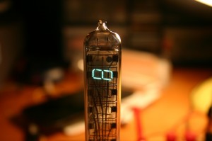
I then got out one of the russian IV-18 tubes from my collection and hooked it into a breadboard, and ran 5v into a trimpot and then to the filament, and ran the HV power to the anodes/grid. After some trial and error I finally got it to light up. It seems to like about 60v.

The IV-18 tubes more than are worthy of a close-up. I am quite enamoured with them.

Comments Off on HV-PSU | Alarm Clock Project, Electronics, Hardware


